4 / 10 / 2025
tutorial: ChopMesh V1.4.0 User Manual – Interface Operation Section
Introduction
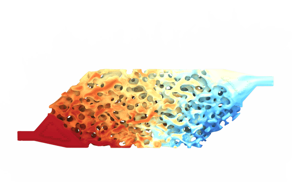
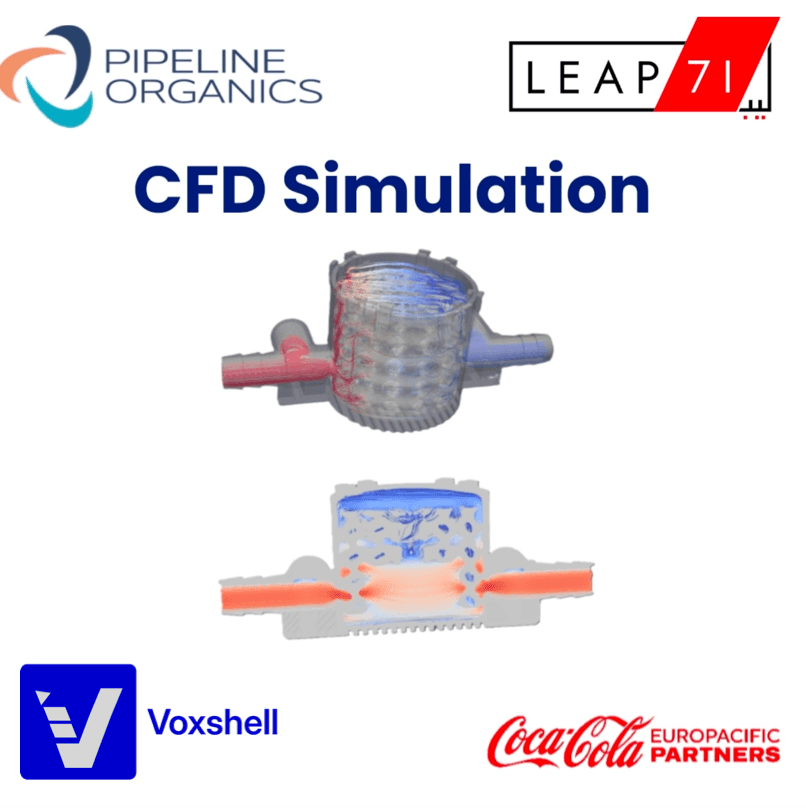
ChopMesh V1.4.0 is a mesh generation software designed to create high-quality computational grids for CFD and FEA simulations.
Interface
The interface of ChopMesh V1.4.0 consists of two main areas: the left control panel and the right visualization window.

select geometry
ChopMesh V1.4.0 supports multiple geometry formats, including STL, VDB, and implicit representations, allowing users to import a wide range of models for meshing.

Set Mesh Domain
In the domain setup module, users can freely adjust the X, Y, and Z boundaries to define the meshing region.

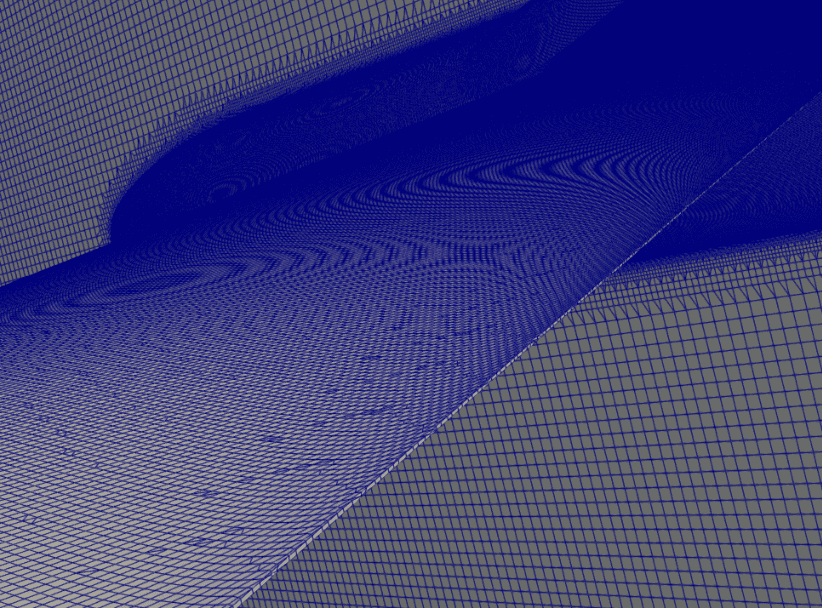
Mesh generation
In the mesh generation and resolution setting section, users can manually define the mesh resolution and the refinement level (0–6). The mesh resolution at level 0 determines the base grid density, where larger values create finer grids and smaller values produce coarser grids. The refinement level specifies how many times the mesh is locally subdivided, with level 0 meaning no refinement and level 6 providing the highest refinement. By combining these two parameters, users can balance mesh quality and computational cost according to their simulation needs. Enabling the Small Feature option allows the software to capture and mesh tiny geometric details more efficiently.


Boundary patch
The next step is Set Boundary Patches. First, open this option and click Apply Boundary Patch Tolerance. Then, click Pick BC and select any point on the surface you want to assign. Finally, click Confirm to complete the boundary patch definition.

Mesh Export

After completing all the required steps, proceed to Mesh Export. In the Select Export Mesh Format option, choose the desired format for your mesh.